Driving an E Ink Spectra 6 panel
E Ink Spectra 6 is a six-colour E-Paper panel that keeps its picture with no power. You can drive one from a small microcontroller with about twenty SPI commands and one status pin. This is the sequence we use in LogCase, and the mistakes we made along the way.
The examples use a 4-inch panel, 400 pixels wide and 600 tall. Other Spectra 6 sizes follow the same steps with a different resolution. The code is plain C99, trimmed from ours. The pin and timing functions (SCL_H/L, SDA_H/L, CS_H/L, DC_H/L, RST_H/L, BS_L, BUSY_READ and delay_ms) depend on your board, so define them for your pins.
What the controller does
Every panel carries its own controller chip. It holds the image in its own memory, makes the high drive voltages and runs the waveform: the series of voltage steps that moves each pigment into place. The panel maker stores the waveform in the controller, so you don’t need to touch it.
The pins
- BS. Tie it low to select 4-wire SPI. Left high, the panel expects 3-wire, 9-bit SPI and none of this code works.
- SCL and SDA. SPI clock and data. There is no MISO; the one data line is bidirectional, but you only write to it.
- CS. Chip select, low while a byte is sent.
- DC. Low for a command byte, high for the data that follows it.
-
RES#. Hardware reset, active low (
RST_LandRST_Hin the code). - BUSY. Low while the controller is working, high when it is idle.
Every message is one command byte followed by its parameters. These functions cover every command, plus a BUSY wait with a timeout. SEND() keeps the command lists below short.
#include <stdint.h>
#include <stdbool.h>
#include <stddef.h>

/* Bit-banged SPI, MSB first, write only. DC low = command, DC high = data. */
static void spi_byte(uint8_t b) {
    for (int i = 0; i < 8; i++) {
        if (b & 0x80) SDA_H(); else SDA_L();
        SCL_H(); SCL_L();
        b <<= 1;
    }
}

static void epd_cmd(uint8_t c)  { CS_L(); DC_L(); spi_byte(c); CS_H(); }
static void epd_data(uint8_t d) { CS_L(); DC_H(); spi_byte(d); CS_H(); }

static void epd_send(uint8_t cmd, const uint8_t *p, size_t n) {
    epd_cmd(cmd);
    while (n--) epd_data(*p++);
}

/* SEND(command, data...) */
#define SEND(cmd, ...) do { \
    static const uint8_t d_[] = {__VA_ARGS__}; \
    epd_send((cmd), d_, sizeof d_); \
} while (0)

/* BUSY: low = working, high = idle. Returns false on timeout. */
static bool epd_wait_idle(uint32_t timeout_ms) {
    while (timeout_ms--) {
        if (BUSY_READ()) return true;
        delay_ms(1);
    }
    return false;
}
On a fast microcontroller you may need a short delay between SCL_H() and SCL_L().
When the panel’s supply is off, BUSY floats and can read as idle, which looks exactly like a finished refresh. Make sure the panel is powered before you trust BUSY. If you bias the line, use a weak pull-down, so an unpowered panel reads as busy and the wait times out.
The sequence
An update goes reset, set-up, picture, power on, refresh. A board that stays powered then switches the panel off and lets it sleep.
1. Reset
static bool epd_reset(void) {
    BS_L();                    /* 4-wire SPI */
    RST_L(); delay_ms(20);
    RST_H(); delay_ms(120);    /* 20 ms minimum, 120 ms for margin */
    return epd_wait_idle(1000);
}
Hold RES# low for 20 ms and release it. The controller needs at least 20 ms before it accepts commands; we wait 120 ms, then for BUSY.
Reset at the start of each update, before the picture goes in, and not after. A reset after the image has been loaded corrupts it in the controller’s memory. The panel is not damaged, and sending the image again fixes it, but it is easy to mistake for a hardware fault. On ours it showed up as a regular pattern of wrong pixels across the top of the picture, about one pixel in twenty, the same every time.

2. Set up the controller
static void epd_init_registers(void) {
    SEND(0xAA, 0x49, 0x55, 0x20, 0x08, 0x09, 0x18);   /* unlock        */
    SEND(0x00, 0x5F, 0x69);                           /* panel setting */
    SEND(0x03, 0x00, 0x54, 0x00, 0x44);               /* power-off seq */
    SEND(0x60, 0x02, 0x00);                           /* timing        */
    SEND(0x30, 0x08);                                 /* clock (PLL)   */
    SEND(0x50, 0x3F);                                 /* VCOM, data    */
    SEND(0x61, 0x01, 0x90, 0x02, 0x58);               /* 400 x 600     */
    SEND(0xE3, 0x2F);                                 /* power saving  */
    SEND(0x84, 0x01);                                 /* as given      */
}
These values match the open-source drivers listed at the end. 0xAA unlocks the command set, and 0x61 sets the resolution: 400 is 0x0190 and 600 is 0x0258. Some commands, such as 0x84, are barely documented. Send them as given.
Don’t read registers back to check them. On this controller, sending a register’s command byte in order to read it runs that command, so a read can change the settings, and a stray one at the wrong moment can leave the panel blank. Treat the bus as write-only and use BUSY for status.
3. Send the picture
The controller takes 4 bits per pixel, two pixels to a byte, with the left pixel in the high nibble. Rows run from top to bottom.
| Colour | Code |
|---|---|
| Black | 0x0 |
| White | 0x1 |
| Yellow | 0x2 |
| Red | 0x3 |
| Blue | 0x5 |
| Green | 0x6 |
enum { BLACK = 0x0, WHITE = 0x1, YELLOW = 0x2,
       RED   = 0x3, BLUE  = 0x5, GREEN  = 0x6 };   /* 0x4 is not used */

/* Two pixels per byte: the left (even x) pixel in the high nibble. */
static inline uint8_t epd_pack(uint8_t left, uint8_t right) {
    return (uint8_t)(((left & 0x0F) << 4) | (right & 0x0F));
}

/* len = 400 x 600 / 2 = 120,000 bytes */
static void epd_write_image(const uint8_t *buf, size_t len) {
    epd_cmd(0x10);   /* DTM */
    while (len--) epd_data(*buf++);
}
A full picture is 120,000 bytes, sent after a single DTM command (0x10). It goes straight into the controller’s memory, so the microcontroller needs no frame buffer: ours keeps 1 KB and streams the rest. epd_data() toggles CS for every byte, and the controller accepts that. Turning a photo into these six colours is a separate job, usually done with dithering before the data reaches the panel.
4. Power on and refresh
#define MIN_REFRESH_MS 15000   /* ours takes about 19 s at room temperature */

static bool epd_power_on_and_refresh(void) {
    SEND(0x01, 0x3F);                     /* PWR   */
    SEND(0x05, 0x40, 0x1F, 0x1F, 0x2C);   /* BTST1 */
    SEND(0x08, 0x6F, 0x1F, 0x1F, 0x22);   /* BTST3 */
    SEND(0x06, 0x6F, 0x1F, 0x17, 0x17);   /* BTST2 */
    epd_cmd(0x04);                        /* PON   */
    if (!epd_wait_idle(1500)) return false;
    SEND(0x06, 0x6F, 0x1F, 0x17, 0x27);   /* BTST2 */
    SEND(0x12, 0x00);                     /* DRF   */

    uint32_t t = 0;
    while (!BUSY_READ()) {
        if (t++ >= 30000) return false;   /* never finished */
        delay_ms(1);
    }
    return t >= MIN_REFRESH_MS;           /* idle too soon: failed */
}
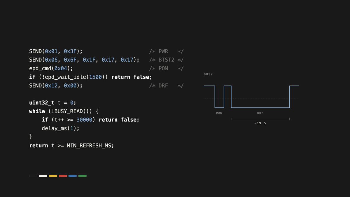
PWR and the three booster settings prepare the power stage. BTST3 goes before BTST2, as in the open-source drivers. PON starts the power stage, and BUSY goes high when the drive voltages are ready; 1.5 s has always been enough on our boards. BTST2 is sent again with a different last byte, and DRF starts the refresh.
The panel flashes through several colours during the refresh, which takes about 19 seconds on the 4-inch panel. That is expected. Time it. If BUSY returns to idle well before the panel’s normal refresh time, treat it as a failure: the refresh stopped part-way, or the panel was not powered at all. Refresh time depends on the panel and on temperature, so measure yours and set the minimum with margin.
5. Power off and sleep
static void epd_sleep(void) {
    SEND(0x02, 0x00);   /* POF */
    epd_wait_idle(1000);
    SEND(0x07, 0xA5);   /* DSLP; 0xA5 is a check code */
}
POF switches the drive voltages off, and DSLP puts the controller into deep sleep. The usual way out of deep sleep is a hardware reset, so the next update starts again from step 1. The picture stays on the panel either way.
LogCase skips this step. The case has no battery and runs only on power from the iPhone’s NFC field, so the power fades once the refresh is done.
Further reading
The open-source drivers bb_epaper and zy_e_album drive the same panel and cover other sizes too. For how the pigments move, see our technology page.
E Ink and Spectra are trademarks of E Ink Holdings Inc.